 Using a laser stripping technique, the SEEMS facility can be placed between the SNS linac and the accumulator ring. The building footprint will approximate be 100 x 100 ft2 (30 x 30 m2), and will be placed on the west side of the accumulator ring, on the north side of the SNS water tower. This will keep the facility well separated from any neutron background of the SNS target buildings, and keep the proton transport line as short as possible. A plot showing the location of the SEEMS facility is shown in Fig. 1.
For µSR, the high flux of the proposed facility would support conventional, surface muon beamlines, as well as more specialized decay muon beamlines and low-energy muon beamlines. The most common type of µSR beamline is generated from pions that decay at rest on the surface of the target, leading to their designation as ‘surface’ muon beamlines. This means that the ideal configuration is that the µSR beamlines originate at the ±90° beamline positions, relative to the incoming proton beam. Surface muon beamlines are built to be short (relative to neutron beamlines, for example) to minimize any spatial broadening of the muon pulse and to minimize decay of the muons in flight. As charged particles, the muons are easily steered and filtered in the beamline, and readily stopped in the sample. Typical stopping distances are < 1mm for surface muon beams in metals, allowing small samples to be easily measured in a typical µSR experiment.
The ideal placement for end stations receiving high-energy neutron beams for SEE testing are at the ±30° beamline positions. These stations are each 9×3 m (interior area) testing stations offering two irradiation positions, one for device testing and one for system testing. The position for component irradiation will be located at about 5 m from the target, and the beam line will provide fluxes of 10 MeV or greater neutrons of up to 107 n/cm2/s onto areas as large as 20 × 20 cm2. The position for system irradiation will be located at the far-target position (14 m from the target). At the system position, it will be possible to deliver peak above-10 MeV fluxes up to 1.3×10⁶ n/cm2/s over an area of 0.56 × 0.56 m2 (propagation of component testing beam to the back of enclosure). Alternately, it will be possible to deliver a beam over an area of 1 × 2 m2 with a peak above-10-MeV fluxes up to 2×10⁵ n/cm2/s. At these flux levels and beam dimensions, the peak integral in-beam neutron currents are equivalent for all irradiation conditions. Neutron current / flux can be reduced by multiple methods including reducing the laser stripping duty factor.
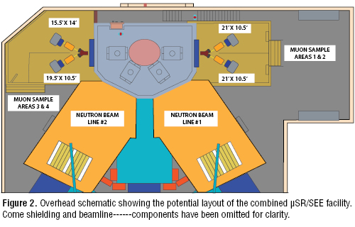
This makes the placement of the µSR beamlines highly compatible with the SEE testing stations, and the high flux means that multiple µSR beamlines can originate from the same beam port around the target, as is done in other facilities around the world. It is envisioned that 4 µSR beamlines would be present at the facility, two on each side of the target vessel. A schematic view of the beamlines is shown in Fig. 2.